Guide to GD&T
The base of effective rules is the typical criterion. GD&T is such a criterion for setting up layout and production. In this article, we’ll present the GD&T definitions and also terms, as well as the chart of GD&T symbols.
Table of Contents
What is GD&T?
GD&T (Geometric dimensioning and tolerancing) is a system made use of to specify and communicate the tolerances for design layouts and computer-generated 3D solid versions. The symbolic language in GD&T defines the geometry as well as allowable variation or mistake, it can define the demands of accuracy and precision of the CNC machined parts.
Exactly How GD&T Functions?
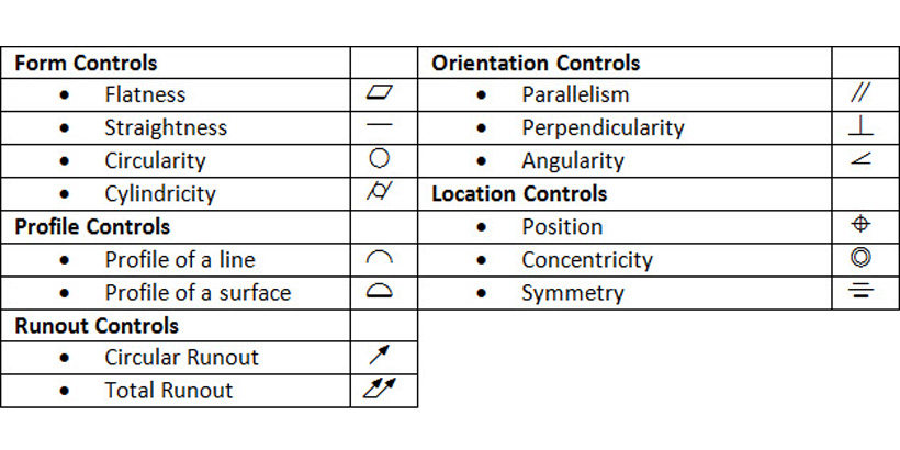
The comprehensive features with dimensions require to be revealed on engineering drawings, the tolerance restricts the minimum as well as optimum appropriate worth. The GD&T language consists of measurements, tolerances, icons, definitions, conventions, as well as rules to set the best variations of location, orientation, size, as well as kind of each function of the design version, which supplies excellent advantages and versatility for manufacturing. The GD&T signs are categorized right into 5 teams as below. Look into these GD&T terms and also definitions.
Form controls
- Straightness: a tolerance that regulates the form of a line somewhere on the surface or the function.
- Flatness: a sign that references how to level a surface is no matter any other datums or attributes.
- Circularity: likewise called satiation, a 2-Dimensional tolerance that explains exactly how close an item must be to a true circle.
- Cylindricity: a 3-Dimensional resistance that manages the total type of a cylindrical function to guarantee that it is round enough and straight sufficient along its axis.
Profile controls
- Line profile: a two-dimensional tolerance variety that restricts the amount of error for line components about their real profile.
- Surface profile: a three-dimensional tolerance limits the amount of mistake a surface area can have about its real profile, relates to all line aspects collectively.
Orientation controls
- Angularity: specifies a resistance area defined by two parallel aeroplanes at the defined angle apart from 90 levels from a datum aircraft or axis within where the surface area or the axis of the attribute should lie.
- Perpendicularity: a three-dimensional geometric tolerance that manages how much an axis, surface area, or plane can deviate from a 90-degree angle.
- Parallelism: the problem of a surface or facility aircraft equidistant whatsoever points from a datum aircraft, or an axis.
Location controls
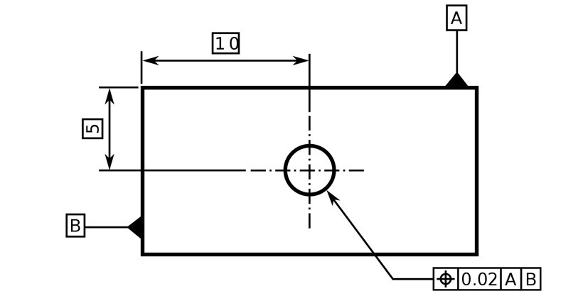
- Position: the location of one or more attributes of dimension about one another or to one or more information.
- Concentricity: a condition in which the axes of all cross-section components of a function’s surface area of revolution are common to the axis of a datum feature.
- Symmetry: a three-dimensional geometric resistance that controls how much the typical factors in between two features may differ a defined centre plane or axis.
Runout controls
- Circular runout: can be defined as two-dimensional geometric tolerance that controls the form, orientation, and also place of multiple samples of a round part as it revolves.
- Total runout: includes tolerance control along with the entire size of, as well as between, 2 fictional cylindrical tubes, manages cumulative variations in circularity, coaxial, straightness, taper, angularity, and also account of a surface.
GD&T Symbols Graph
Below is a GD&T Symbols Chart including usual GD&T symbols that can be utilized in your drawing:


